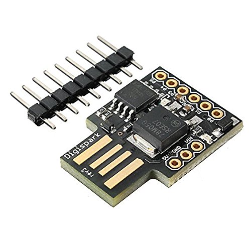
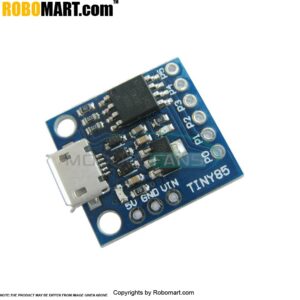
The ATtiny85 based mini development board is similar to the Arduino, but cheaper and smaller (of course a bit less powerful). With a whole host of shields to extend its functionality and the ability to use the familiar Arduino IDE, this ATTINY85 USB Development Board is a great way to jump into microcontroller electronics.
ATtiny85 based microcontroller development board come with the USB interface. Coding is similar to Arduino, and it uses the familiar Arduino IDE for development. This is a digispark clone.
It has 6 port with several functions. Depending on the programming (with Arduino IDE) can it have 6 digital I/O, 4 analog inputs or 3 PWM outputs. It can be powered by a USB port or an external power supply of 6-35V DC.
Features :
- Support for the Arduino IDE 1.0 + (OSX/Windows/Linux).
- Power via USB or External Source or 7-16 v to 5 v (automatic selection).
- The On ? board, 150 ma 5 v Regulator.
- Built ? in USB and serial was debugging).
- 6 I/O Pins (2 inform the for USB only if your program actively communicates over USB, otherwise you can use all 6 even if you are programming via USB).
- 8 k Flash Memory (about 6 k after bootloader).
- The I2C and SPI (vis USI).
- PWM on 3 pins (more possible with Software PWM).
- The ADC on 4 pins.
- The Power LED and the Test/Status leds.
